Bus Pirate and SCP1000
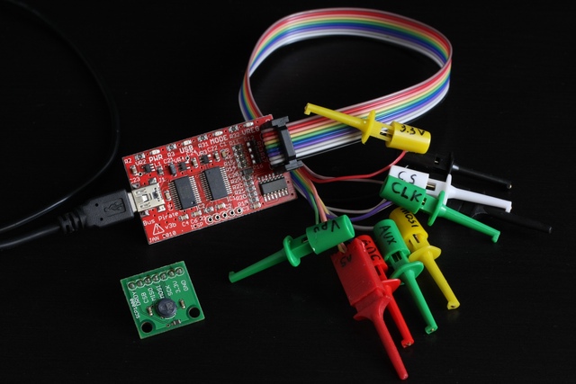
I decided to learn how to use my Bus Pirate (v3) by getting it to talk to an SCP1000 chip that I’ve had for a while but not got round to using. The SCP1000 is a very accurate barometric pressure sensor with an SPI interface, mine is on a handy breakout board and came from Sparkfun. The datasheet has the details.
For the first step I found it pretty much vital to label each of the connectors on the end of the Bus Pirate cable as tracking down which is which was taking too long.
Having done that I hooked them up as follows:
GND   -  GND
3.3V  -  3.3V
CLK   -  SCK
MOSI  -  MOSI
MISO  -  MISO
CS    -  CSB
AUX   -  DRDY
I’m talking to the Bus Pirate using a computer running Ubuntu Linux. Plugging it in results in a new serial device, probably /dev/ttyUSB0 if you have no other USB-serial devices plugged in (an Arduino counts). I use Screen to connect to the serial device like so: screen /dev/ttyUSB0 115200. To disconnect and close screen type ctrl-a followed by k.
Once connected there was nothing to see, so I hit return to make a prompt appear:
HiZ>
The bit before the > is the current mode. HiZ means high impedance, none of the lines will allow current to flow so it’s safe to connect up.
Type ? to see what’s possible:
HiZ>?
MENUS
? Help
I Status info
M Bus mode
B Terminal speed
O Data display format
V Check supply voltages
F Frequency count on AUX
G Frequency generator/PWM on AUX
C AUX pin assignment
L Bit order
P Pullup resistors
= HEX/DEC/BIN converter
~ Self test
# Reset
$ Bootloader
SYNTAX
A/a/@ AUX output toggle H/L/read
W/w Power supply toggle on/off
d (D) Measure voltage on ADC probe (continuous)
[ ({) Start (with read)
] or } Stop
R or r Read byte
0b Write BIN byte
0h or 0x Write HEX byte
0-255 Write DEC byte
, Delimiter (also space)
& 1uS delay
: Repeat (r:2, 0x0a:4, &:20, ^:2, etc.)
(#) Run macro, (0) for macro list
RAW BUS OPERATIONS
/\ Clock H/L
-/_ Data H/L
. Read data input pin state
^ Clock tick
! Read bit
HiZ>
Type M to see the mode menu:
HiZ>M
1. HiZ
2. 1-WIRE
3. UART
4. I2C
5. SPI
6. JTAG
7. RAW2WIRE
8. RAW3WIRE
9. PC KEYBOARD
10. LCD
(1) >5
Mode selected
I want SPI so typed 5. I’m then asked for various settings for SPI:
Set speed:
 1. 30KHz
 2. 125KHz
 3. 250KHz
 4. 1MHz
(1) >1
The SCP1000 datasheet says it can go up to 500kHz. Speed is not of the essence so I just went with the slowest.
Clock polarity:
 1. Idle low *default
 2. Idle high
(1) >2
I picked Idle high based on the SPI examples in the datasheet. It probably works either way round.
Output clock edge:
 1. Idle to active
 2. Active to idle *default
(2) >1
Input sample phase:
 1. Middle *default
 2. End
(1) >2
I picked the above two settings based on the following from the datasheet: “Bits from MOSI line are sampled in on the rising edge of SCK and bits to MISO line are latched out on falling edge of SCK.”
Select output type:
 1. Open drain (H=Hi-Z, L=GND)
 2. Normal (H=3.3V, L=GND)
(1) >2
Open drain isn’t mentioned anywhere in the datasheet, I went with normal.
READY
SPI>
Good to go. The mode light should now be on and probably also the VREG one.
I hooked up the Bus Pirate’s Aux line to the DRDY pin. This one goes high when there’s data ready to read. I can check for this by typing an @.
SPI>@
AUX INPUT/HI-Z, READ: 0
Nothing to read yet. Not surprising because I haven’t told it which sampling mode to use.
The SCP1000 has four modes: high resolution, high speed, ultra low power and low power with an external trigger. All fairly self explanatory, I want high resolution. Communication is done by reading and writing to numbered registers which are either 8 or 16 bits wide. They’re all detailed in the datasheet. All SPI communication starts with a byte that has the register number in the top six bits, bit seven is 0 for reading or 1 for writing and bit eight is always 0. The following bytes are then either the data to write or 0xFF when reading.
So to engage high resolution mode I need to write 0x0A to register 0x03. The register byte is arranged like so:
0x03  = 000011
Write &       1
0 Pad &        0
      = 00001110 = 0x0E
On the Bus Pirate a { means start the protocol by enabling the CS pin and I want to read after every write. } means stop. Commands can be strung together on one line by separating them with a space. So I proceed like so:
SPI>{ 0x0E 0x0A }
CS ENABLED
WRITE: 0x0E READ: 0x00
WRITE: 0x0A READ: 0x00
CS DISABLED
Now to check the DRDY pin:
SPI>@
AUX INPUT/HI-Z, READ: 1
It’s high! So there’s readings to read. I’ll start by reading the temperature in register 0x21 which is 16 bits wide.
0x21  = 100001
Read  &       0
0 Pad &        0
      = 10000100 = 0x84
I write two 0xFF bytes just to cause it to read the result bytes, they don’t actually do anything.
SPI>{ 0x84 0xFF 0xFF }
CS ENABLED
WRITE: 0x84 READ: 0x00
WRITE: 0xFF READ: 0x01
WRITE: 0xFF READ: 0xB3
CS DISABLED
Ta da! It’s a balmy 0x01 0xB3. Converting the temperature is explained in the datasheet with examples, but basically it’s MSB first, 14 bit, twos-complement then divide by 20. So the above comes to 21.75 degrees centigrade.
Getting the pressure involves reading two registers, 0x1F for the top part (8 bits wide) and 0x20 for the bottom part (16 bits wide).
SPI>{ 0x7C 0xFF }
CS ENABLED
WRITE: 0x7C READ: 0xFF
WRITE: 0xFF READ: 0x06
CS DISABLED
SPI>{ 0x80 0xFF 0xFF }
CS ENABLED
WRITE: 0x80 READ: 0x00
WRITE: 0xFF READ: 0x25
WRITE: 0xFF READ: 0x5E
CS DISABLED
The result is 0x06 0x25 0x5E. Again MSB first and it’s an unsigned integer so I just stick the bytes together then divide by 4 to get the reading in Pascals, which is 100695.5.